|
The Front Hydraulic Winch
If you want to winch a lot its a choice between direct mechanical from the engine, or compressed air, or hydraulic,
or electric. Mechanical is risky as you cannot tell when its overloaded (well, only by the rope snapping, unless it has some
fancy overload gear). Air is the best as it stalls out and stops using power, but there is no room on a small vehicle
for a compressor, so that leaves hydraulic and electric.
Electric is very simple. The vehicle is covered in 12volt systems, some of which are high current, so the electric winch
pops right on. But we found the limit of electric motors in Robot Wars. Under sevear loads the motor heats up and up until
somthing goes pop. Worse still, it takes ages to get that heat back out! (time to make your mark on the world with a cheap
water cooled motor armature).
If you have a hydraulic systems built into your machine (because you are putting the winch on tractor) then a
hydraulic winch is a real easy install, but land rovers only have the power steering pump? Its low power, so the
only option is to fit a large pump. The front of the crank shaft is favorite on many industrial machines. So Enter a
Serious amount of work and careful engineering!
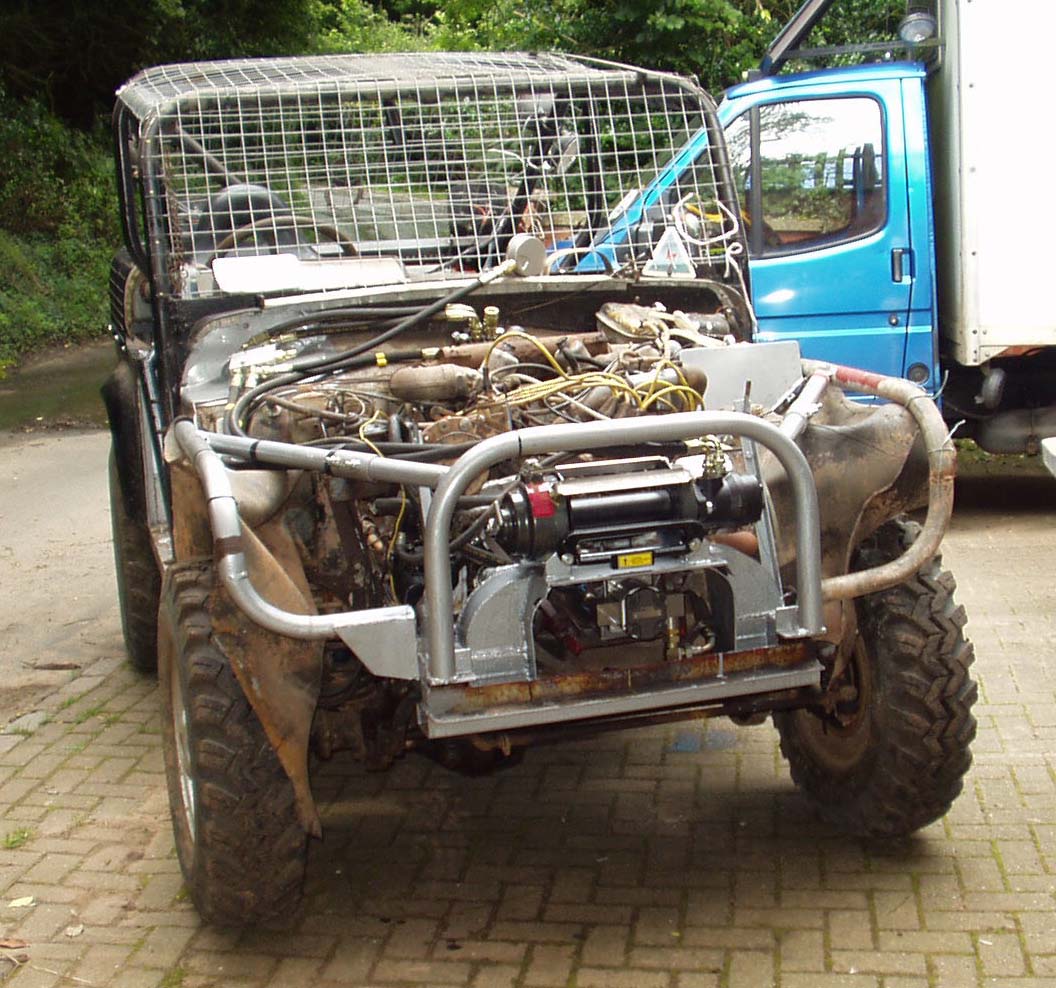
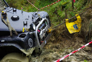
Above is the hydraulic winch fited. We still run the 1972 Range Rover under carriage, so the engine very far forward.
By the time the drive boss is in, plus rubber coupling and dog box, the pump is right behind the front bumper. This forces
the winch position up onto a bridge. The risk is a greater forward rotation on the vehicle under heavy load. The advantage
is less chance of imersing the winch in water, plus you dont have to bend down to operate the winch gears.
Below is the plate the pump fits on.
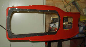
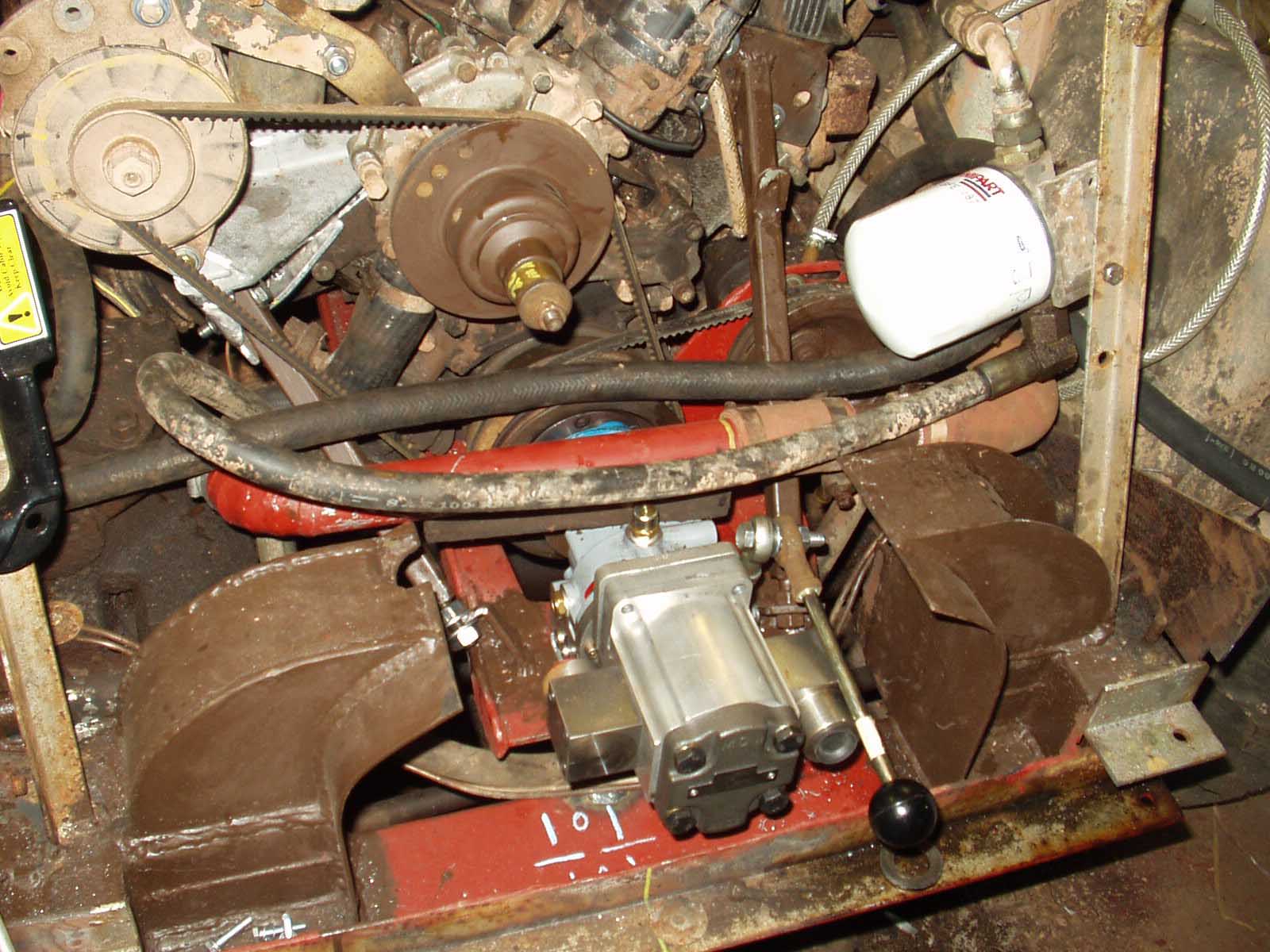
Above is the hydraulic pump platform. This red plate goes between the sump and engine block to form a mounting platform
for the hydraulic pump and its dog clutch housing. The smaller hole in the plate is for the front pulleys. This plate
sticks out the front of the engine quite a way, so two braces run from its end to the cylinder heads.
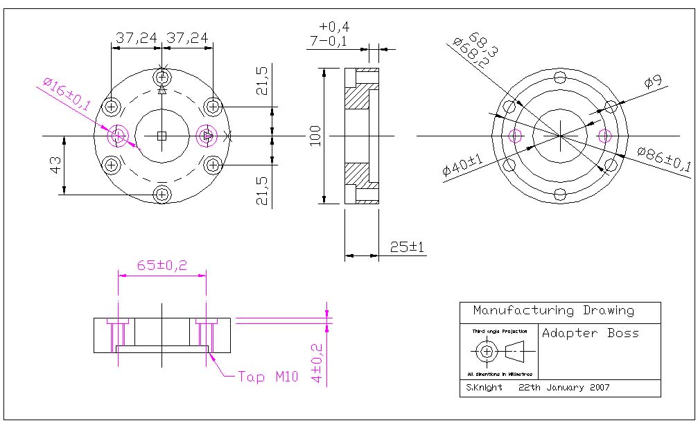
Below is an engineering drawing of the drive boss which bolts to the rover V8 crank shaft. It is readable if you click
on it!
Six holes bolt through the pulley holes, the other two holes are for the rubber coupling. If you want to use this drawing
thats fine, but have a good measure of your V8 first.
First brilliant mod to the hydraulic winch was the sliding hawse. This is so good that David (goodwinch) is manufacturing
it! (I'm an Inventor now) The device lets you pull sideways without all the rope jamming up one side of the winch drum. Look
out for it on his web site or in cool publications like Spetember 2010's edition of Total Off road Magazine :o)
Second usefull modification has been remote control for the speed levers. Using two bycicle gear change levers, the winch
can be put in low speed, high or free from the drivers seat. ( Thanks to HOFS for that one! )
|


